
Ian Ashdown, P. Eng., FIES, Senior Scientist, SunTracker Technologies Ltd.
Published: 2016/04/30
This blog article has a somewhat frustrating history. About a year ago, I was asked to volunteer my time to write a primer of light and color as it relates to sports lighting regulations. I was told the name of the organization I was volunteering my time for, but I did not pay much attention — it seemed like a good cause.
I should have perhaps paid more attention before agreeing to volunteer — the Green Sports Alliance is not the poorest of socially responsible organizations.
Upon completing the primer, I was told that it was far too technical for its intended audience. Hopefully, you as my readers will disagree.
Sports Lighting Requirements
Sports lighting has specific requirements that may not be familiar to many lighting designers. The Illuminating Engineering Society publishes detailed recommendations related to sports lighting (IES 2009, 2010a, 2015), while various professional sports organizations have their own specific requirements (for example, FIFA 2007, FIH 2011, NCAA 2010a and 2010b, and Lewis and Brill 2013).
Illuminance
In sports lighting, there are two forms of illuminance measurements that are of interest: horizontal illuminance and vertical illuminance.
Horizontal illuminance is typically measured on a horizontally oriented imaginary surface one meter (~3 feet) above the field surface. Multiple measurements are usually measured (or calculated during the lighting design phase) on a grid. The National Football League, for example (Lewis and Brill 2013), specifies a grid spacing of 5 meters (~16 feet).
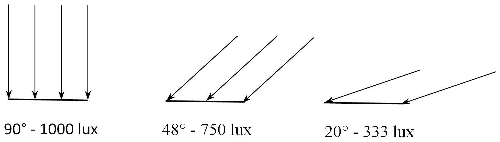
Vertical illuminance is measured on a vertically oriented imaginary surface. Unlike horizontal illuminance, both the position and orientation of the vertical surface must be specified. To understand why, consider a vertical surface illuminated by a single light source (FIG. 1).
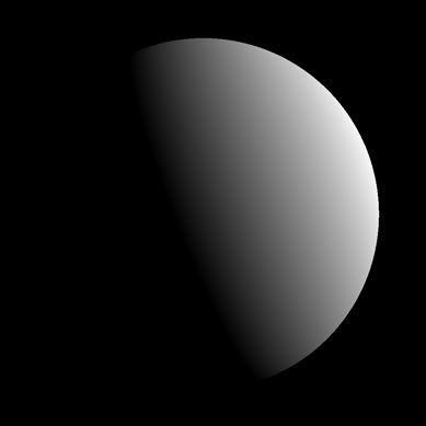
As the angle of illumination decreases, the lumens per square meter decrease as well, until at grazing angles the surface is barely illuminated at. This can clearly be seen with a sphere illuminated by a single light source (FIG. 2).
In practice, there will be multiple luminaires illuminating the field, each of which will contribute to the illumination of a vertical surface — such as a player’s face. It is therefore important to ensure that the vertical illuminance is within minimum and maximum limits so that the players’ faces and team numbers can always be seen.
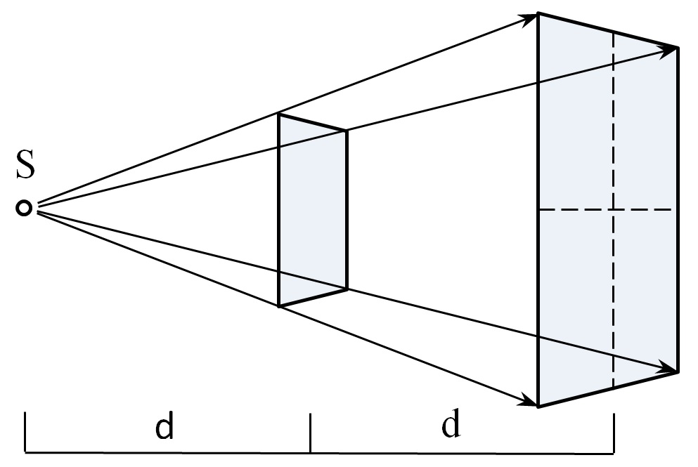
With this in mind, the “falloff” in illuminance with distance from a single luminaire must also be kept in mind. As shown in FIG. 3, a light source S illuminates two imaginary surfaces, the first one at distance d from the light source, and the second at twice the distance. Both surfaces receive the same amount of light (lumens) from S, but the area of the second surface is four times that of the first. Consequently, its illuminance (lumens per square meter) is only one-quarter that of the first surface.
Generalizing this to any distance, it is easy to see that the illuminance from a single luminaire will decrease, or “fall off,” according to the square of the distance. This is the basis of the inverse square law used by lighting designers.
Finally, “TV illuminance” is occasionally used for television broadcasting purposes (IES 2015). It is the illuminance measured at a position on the playing field when the illuminance meter is aimed directly at a specified camera position.In practice, of course, multiple luminaires are used to (more or less) evenly illuminate a playing field.
Uniformity
Uniformity of illumination is important for sports. It enables both the players and the spectators to easily follow the action, and it provides consistent lighting for the television cameras and photographers. Sports field lighting for internationally televised events must meet exacting standards, while more leeway is generally allowed for other events.
There are three measures (or more properly metrics) used to specify the desired uniformity of horizontal and vertical illuminance on the playing field. The simplest metric is the maximum-to-minimum ratio, commonly referred to as the uniformity ratio. Using NFL requirements as an example, horizontal illuminance is designated Eh, and so the uniformity ratio is expressed as Ehmax/Ehmin. Using a measurement grid for the playing field with 5-meter spacing, this ratio for all measurement values must be 1.4:1 or less.
Again using the NFL requirements, vertical illuminance is designated Ev, and the uniformity ratio Evmax/Evmin must also be 1.4:1 or less.
The NFL requirements go further in specifying that: 1) the ratio of the average horizontal illuminance Ehavg to average vertical illuminance Evavg as seen from camera #1 (that is, with each vertical surface facing the camera) must be between 1.0 and 2.0, with a target value of 1.5; 2) the ratio of vertical illuminances at any point on the field between the four imaginary vertical surfaces facing the four sides of the field shall be between 0.6 and 0.9; and 3) the average vertical illuminance Evavg facing towards camera #1 shall not be less that Evavg for the other three orthogonal (that is, right-angle) orientations. In other words, it can get complicated.
The second uniformity metric is the coefficient of variation, designated CV. Without delving into the mathematics of this statistical value, it can be likened to the point spread in sports betting. (If you must know the details, the equation is:
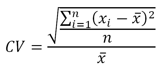
with details left to the interested reader — see [IES 2009, 2015].) It is basically a measure of how “smooth” the lighting distribution is across the playing field.
The third metric is the uniformity gradient, designated UG. It is defined as the ratio between illuminance values between adjacent measuring points on a square grid. Whereas CV describes the average non-uniformity for the entire field, UG describes the maximum non-uniformity. It is particularly important in sports with fast-moving balls and the like, as changes in illuminance can make it more difficult to judge their speed.
Visual Glare
Visual glare occurs when the luminance of the luminaires within the observerís field of view (either a player or spectator) is sufficiently greater than the average luminance to which the observerís eye have adapted. It may cause visual discomfort (in response to which we tend to squint), or it may impair the vision of objects and details (such as past-moving balls and the like).
As a psychophysiological phenomenon, glare is both literally and figuratively “in the eye of the beholder.” All lighting researchers can do is present subjects in a laboratory with a lighting setup and ask them to rate the glare on a subjective scale. While it cannot be directly measured in the field, a glare rating metric, designated GR, can be calculated (typically at the design phase) in accordance with CIE 112-1994, Glare Evaluation System for Use with Outdoor Sports and Area Lighting (CIE 1994).
Central to these calculations are five parameters:
- The luminances of the luminaires as seen by the observer;
- The angular extent of the luminaires in the observerís field of view;
- The position of the luminaires in the observerís field of view relative to the line of sight;
- The number of luminaires in the observerís field of view; and
- The average luminance of the observerís entire field of view.
It is important to note that the GR metric depends on where the observer is positioned relative to the luminaires, and the line of sight direction. Consequently, any GR requirements must specify these parameters. The NFL requirements, for example, require that GR be less than 40 for all main cameras (Lewis and Brill 2013).
Color
Many sports organizations specify the allowable correlated color temperature, designated CCT, for sports field lighting. For example:
| Organization | CCT |
| FIFA | = 4000K |
| FIH | > 4000K |
| NCAA | > 3600K |
| NFL | 5600K (alternatively 5000K to 7000K) |
where the symbol ‘K’ represents kelvins (where one kelvin is equal to one degree Celsius).
To put these numbers into context, quartz halogen and warm white LED lamps typically have CCTs of approximately 3000K, metal halide lamps typically have CCTs of 4000K, and daylight LED lamps typically have CCTs of 5000K.
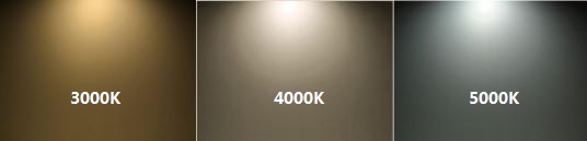
Our eyes adapt quite well to light sources with different CCTs, ranging from 2700K for 100-watt incandescent lamps to 10000K for the blue sky. Even though the light itself may look colored (FIG. 8), objects seen under these light sources appear to have approximately the same colors, with whites looking white.
The same is not true with television and digital cameras, however, which must be adjusted (color-balanced) to display the colors we expect to see. This is why it is important that all the luminaires in a sports lighting installation have approximately the same CCT. If they do not, the television cameras will display annoying color shifts as they pan across the field.
Many sports organizations also specify the minimum allowable color rendering index, designated CRI, for sports lighting. For example:
| Organization | CRI Ra |
| FIFA | = 65 |
| FIH | > 65 |
| NCAA | > 65 |
| NFL | = 90 |
where the CRI Ra metric is a measure of the average color shift of various colors viewed under the light source when compared to viewing the colors under an incandescent or daylight source with the same CCT. A detailed explanation of color rendering is beyond the scope of this introductory chapter, but the topic is fully explained in CIE 13.3-1995, Method of Measuring and Specifying Colour Rendering Properties of Light Sources (CIE 1995).
In general, a minimum CRI of 65 is merely adequate, and is representative of what could be achieved with high-wattage metal halide lamps. With today’s solid-state lighting, a minimum CRI of 80 or greater is common, and CRIs of 90 and above are preferred.
It must also be emphasized that Ra metric represents the average color shift. Solid-state lighting products may also specify a CRI R9 metric, which represents the color shift specifically for red colors. A high R9 value is desirable, especially where team outfits feature saturated red colors.
In terms of television broadcast cameras, a more appropriate color rendering metric is the Television Lighting Consistency Index TLCI-2012 (EBU 2014). Like the CRI Ra metric, this is a measure of the average color shift of various colors viewed under the light source; the difference is that the observer is a color television camera rather than a human.
Spectrally Enhanced Lighting
There is some interest in the topic of spectrally enhanced lighting for sports field applications. For some visually demanding tasks, the recommended illuminance values can be reduced through the use of light sources with high blue content. A full discussion is presented in IES TM-24-13, An Optional Method for Adjusting the Recommended Illuminance for Visually Demanding Tasks Within IES Illuminance Categories P through Y Based on Light Source Spectrum (IES 2013).
It could be argued TM-24-13 can be applied to sports lighting, as it defines (p. 3) “visually demanding tasks” as “… tasks that are based on the ability to discern visual detail to ensure speed and/or accuracy.” In this situation, “visual detail” could be interpreted as a fast-moving ball or hockey puck.
Furthering the argument, TM-24-13 applies to illuminance categories P through Y, which the IES Lighting Handbook, 10th Edition (IES 2010a) defines in Table 4.1, Recommended Illuminance Targets, as interior and exterior lighting installations where the illuminance targets are in excess of 300 lux. Categories P (average 300 lux) through W (average 3000 lux) specifically include “some sports situations” (without defining them).
There are several problems, however. The first is that most sports organizations specify minimum horizontal and vertical illuminances without taking spectrally enhanced lighting into account. Any sports lighting that reduced these values based on TM-24-13 would not be in compliance with these specifications.
The second problem is that the recommended illuminance targets for sports lighting involving television broadcasting are based on the minimum illuminance requirements of the television cameras. These are of course independent of the human visual system, and so the reduced illuminance values calculated in accordance with TM-24-13 do not apply.
The third problem is the most crucial: the Illuminating Engineering Society issued a lengthy position statement (included in TM-24-13) that unequivocally states (in boldface type), “TM-24 should not be used for the development of energy policy or energy efficiency programs purposes for any lighting applications, as this goes against current IES recommendations.”
Light Pollution
Outdoor lighting illuminates not only objects on the ground, but the overhead sky as well. The International Dark-Sky Association reminds us that this unintentional light pollution threatens professional and amateur astronomy, disrupts nocturnal ecosystems, affects circadian rhythms of both humans and animals, and wastes over two billion dollars of electrical energy per year in the United States alone.
It might seem obvious that sports field lighting is a major contributor to light pollution, but this is true only in a local sense. According to a US Department of Energy study (DOE 2010), stadium lighting contributes a maximum of 6 percent (compared to 48 percent for roadway lighting and 34 percent for parking lot lighting) on a national scale. (This further assumes that the stadium lighting is always on at night.)
| Outdoor Lighting | Percent Lumens |
| Roadway | 48 |
| Parking | 34 |
| Building exteriors | 10 |
| Stadiums | 6 |
| Billboards | 1 |
| Traffic signals | 1 |
On a local scale, however, light pollution from stadiums and sports fields can be a concern, particularly for surrounding residential neighborhoods. This includes not only light that is reflected from the ground and illuminates the sky overhead, but also light trespass and glare from improperly shielded luminaires.
IES TM-15-11, Luminaire Classification System for Outdoor Luminaires (IES 2011a) and the Joint IDA-IES Model Lighting Ordinance (MLO) with User’s Guide (IES 2011b) provide detailed information on designing outdoor lighting systems that minimize unintended light pollution.
References
CIE. 1994. CIE 112-1994, Glare Evaluation System for Use within Outdoor Sports and Area Lighting. Vienna, Austria: Commission International de l’Eclairage.
CIE. 1995. CIE 13.3-1995, Method of Measuring and Specifying Colour Rendering Properties of Light Sources. Vienna, Austria: Commission International de l’Eclairage.
DOE. 2010. 2010 U.S. Lighting Market Characterization, U.S. Department of Energy Building Technologies Program.
EBU. 2014. Tech 3355, Method for the Assessment of the Colorimetric Properties of Luminaires: The Television Lighting Consistency Index (TLCI-2012) and the Television Luminaire Matching Factor (TLMF-2013. Geneva, Switzerland: European Broadcast Union.
FIFA. 2007. Football Stadiums: Technical Recommendations and Requirements, 4th Edition. Zurich, Switzerland: FÈdÈration Internationale de Football Association.
FIH. 2011. Guide to the Artificial Lighting of Hockey Pitches, 6th Edition. Lausanne, Switzerland: International Hockey Federation.
IES. 2009. IES RP-6-09, Recommended Practice for Sports and Recreational Area Lighting. New York, NY: Illuminating Engineering Society.
IES. 2010a. IES Lighting Handbook, 10th Edition. New York, NY: Illuminating Engineering Society.
IES. 2011a. IES TM-15-11, Luminaire Classification System for Outdoor Luminaires. New York, NY: Illuminating Engineering Society.
IES. 2011b. Joint IDA-IES Model Lighting Ordinance (MLO) with Userís Guide. New York, NY: Illuminating Engineering Society.
IES. 2013. IES TM-24-13, An Optional Method for Adjusting the Recommended Illuminance for Visually Demanding Tasks Within IES Illuminance Categories P through Y Based on Light Source Spectrum. New York, NY: Illuminating Engineering Society.
IES. 2015. IES RP-6-15, Sports and Recreational Area Lighting. New York, NY: Illuminating Engineering Society.
Lewis, D., and S. Brill. 2013. Broadcast Lighting: NFL Stadium Lighting. The Design Lighting Group Inc.
NCAA. 2010a. NCAA Basketball Championships Best Lighting Practices. National Collegiate Athletic Association.
NCAA. 2010b. NCAA Best Lighting Practices. National Collegiate Athletic Association.
Appendix A
A.1. What is Light?
A primer on sports lighting must answer the obvious question: what is light? The Oxford English Dictionary, the pre-eminent dictionary of the English language, describes light rather loosely as, “the natural agent that stimulates the sense of sight.” More technically, light is electromagnetic radiation.
What we see as visible light is only a tiny fraction of the electromagnetic spectrum, extending from very low-frequency radio waves through microwaves, infrared, visible light, and ultraviolet to x-rays and ultra-energetic gamma rays. Our eyes respond to visible light; detecting the rest of the electromagnetic spectrum requires an arsenal of scientific instruments ranging from radio receivers to scintillation counters.
Our interest however is solely in visible light — it is what we see when we look at the world.
A.2. Quantifying Light
We can think of light as massless subatomic particles called photons. They are emitted by light sources such as metal halide lamps and light-emitting diodes (LEDs), and travel through space until they encounter physical objects. They may then be reflected, refracted, scattered, or absorbed. Some of those photons will intersect our eyes, enabling us to see (FIG. A1).

The number of photons emitted by a typical light source per second is unimaginably large (think of the number ten followed by 30 to 40 zeroes), and so we express this quantity in lumens, where one lumen is approximately the number of photons emitted per second by a wax candle[1]. A typical light source will emit tens of thousands of lumens.
A.3. Measuring Light
Photons emitted by light sources travel outwards in random directions. When these photons encounter a surface, they illuminate the surface (FIG. A2). From the perspective of the surface, it does not matter where the light comes from; it can be a single light source, multiple sources, or even the entire sky.
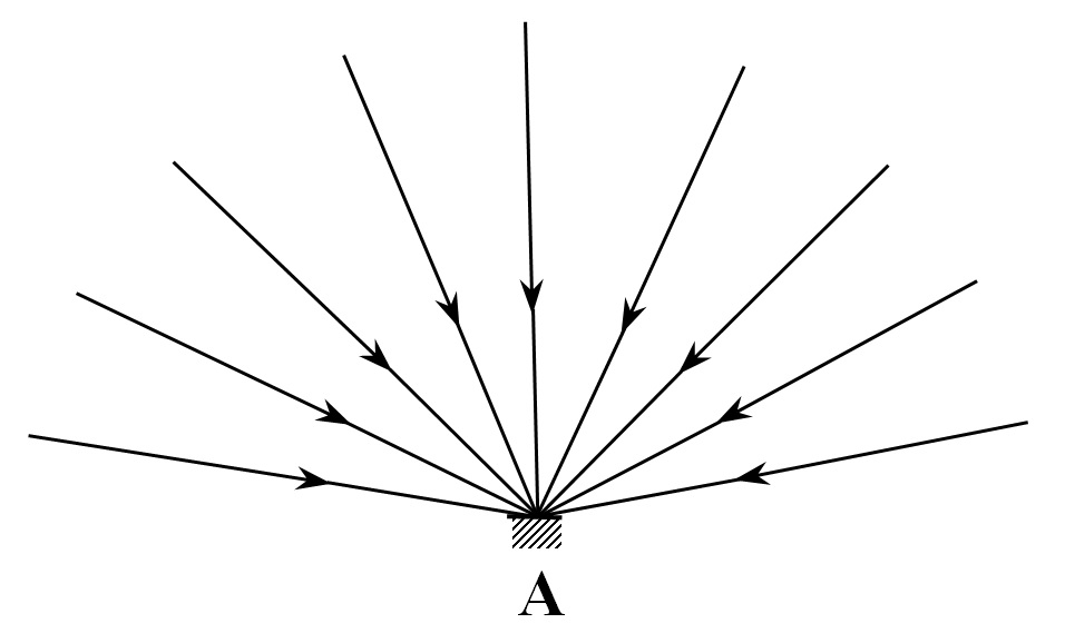
We can use a device called a photometer to measure the number of photons arriving at (incident upon) the surface per second. Of course, this number will depend on the surface area of the photometer’s’ sensor, and so we express the illuminance of the surface in terms of lumens per square meter, or lux. (Lumens per square foot are referred to as a foot-candle — please do not ask why.)
Note that the illuminated surface can be real or imaginary. We can, for example, imagine a “surface” positioned one meter above a physical surface, such as a playing field. The light will of course pass through this imaginary surface, but we can still measure its illuminance with a photometer (which is also called an “illuminance meter” by lighting designers or an “incident light meter” by photographers).
Illuminance is one of the two fundamental units of measurement for lighting designers. While we can measure illuminance with a photometer, we cannot see illuminance. For this, we need another fundamental unit of measurement.
Imagine looking at a computer display. The display consists of an array of a million or so pixels. We see each pixel because some of the photons it is emitting intersect our eye. We can therefore think of these photons as a ray of light, where all of the photons are traveling in the same direction. The more photons per second there are in the ray, the brighter the pixel appears to our eye. This is the luminance of the ray, sometimes referred to as “photometric brightness.”

Textbooks on lighting design typically define luminance as the property of a real or imaginary surface, which leads to the very confusing unit of measurement, “lumens per square meter per steradian,” or lm/m2-sr. It is much easier, however (and just as accurate), to think of luminance as a property of the light ray itself. (The light we see coming from the blue sky, for example, has luminance, but it does not have a real or imaginary surface.)
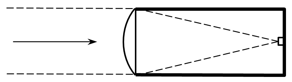
We can easily measure the luminance of a ray by using a telescope to focus a narrow beam of light onto a photometer sensor (FIG. A4). This is a luminance meter; it measures what we see.
[1] A century ago, national standards for measuring light relied on precisely specified wax candles made from spermaceti (whale oil).